Live data from Hacker News

I designed my LED matrix PCB with code

docs.tscircuit.com

41–50 of 68 posts

Re: I designed my LED matrix PCB with code

#41

Atopile is another thing in the circuits-as-code space: https://github.com/atopile/atopile As a half EE/half SWE I think there are significant benefits to circuits as code but I'm not impressed with this one. Atopile has a narrower focus (autorouters are really really hard) and doesn't use as many buzzwords. Like why on earth does a "web first approach" matter at all for hardware development? But also, GUI tools are…

I don't know why anyone wants to shove big heavy applications into browsers. Are they imagining you'd use your phone for this? Are we not teaching kids how to publish desktop applications these days or what?

It's just not that we are imagining that people will be using phone to build PCB's, we also have a cli which perform better than the browser playground!

https://docs.tscircuit.com/intro/quickstart-cli

Re: I designed my LED matrix PCB with code

#42
post #37

Earlier quoted context omitted.

PCB layout is as much art and black magic as it is science. I'm not sure why you dismiss the complexity so easily, this definitely is not just a matter of applying Maxwell's equations.

Layout is a puzzle, especially with particularly high density layouts, but some of this is ameliorated by high layer count and fine trace/space boards becoming cheaper. Definitely not black magic. RF layout is black magic, let's not steal their thunder here.

High speed PCBs are RF. At high enough frequencies, traces become waveguides, and the result cannot be predicted analytically. Simulation is your only light in this mess.

Re: I designed my LED matrix PCB with code

#43
post #29

Earlier quoted context omitted.

> I don't see circuit-as-code taking off with humans anytime soon I don't agree with this. Circuits aren't really anything more complex than anything else humanity has had to figure out. Most knowledge in this area seems solvable. Maxwell's equations have been known for a century. For whatever reason, Software Engineering and Hardware Engineering even though they rely upon the same fundamental physics, are so very di…

> For whatever reason, Software Engineering and Hardware Engineering even though they rely upon the same fundamental physics Software engineering isn't a thing besides being an ego title. Software is "ship now, patch later" Hardware is engineered, it must be correctly designed from the beginning and cannot be easily modified in the field

[dead]

Re: I designed my LED matrix PCB with code

#44
post #40
post #24

A lot of deserved criticism in the comments here tonight, but more generally, I have to ask - what's the deal with all these code/text to CAD/PCB things? There's a half dozen of them in any category, they are all different, they all seem to struggle badly with anything outside of simple examples, none of them appear to consider how things fit together in the real world, you almost never see any of them used for anyth…

I can only talk about my own experience trying to learn FreeCAD for a project[1] I eventually used Build123d for. For me FreeCAD was highly unintuitive. Everything is a chain of operations/modifications on solids(good!) but for some reason it won't let you modify anything but the last element in the chain? I was working on a trackball device so part of the parameters are the size of the trackball you'd use.. This aff…

The only thing FreeCAD has going for it is that it's free, everything else about it is far behind the serious commercial tools.

> Ideally I'd like to see some sort of editing graph where you can see intermediate steps and pick visually parts to operate on for the next step - all underpinned by a concise textual representation that can be versioned.

This is exactly how most[1] commercial 3D CAD packages have worked for at least the last 30 years, they've done it longer than Git or SVN have existed. Specifically everything is represented as a list of operations (sketches, extrusions, chamfers, etc.) and you can freely go back and edit any step, or you can click on any part of a model and see exactly what step was used to generate it.

Some CAD packages will let you see a textual representation, but it's only really useful for scripting when they do. The versioning tools that are built in to any CAD package are far better than trying to work with text.

[1]: Excluding the more obscure CAD packages like Creo that do things differently to fit in to a specific niche.

Re: I designed my LED matrix PCB with code

#45
post #40

Earlier quoted context omitted.

I can only talk about my own experience trying to learn FreeCAD for a project[1] I eventually used Build123d for. For me FreeCAD was highly unintuitive. Everything is a chain of operations/modifications on solids(good!) but for some reason it won't let you modify anything but the last element in the chain? I was working on a trackball device so part of the parameters are the size of the trackball you'd use.. This aff…

The only thing FreeCAD has going for it is that it's free, everything else about it is far behind the serious commercial tools. > Ideally I'd like to see some sort of editing graph where you can see intermediate steps and pick visually parts to operate on for the next step - all underpinned by a concise textual representation that can be versioned. This is exactly how most[1] commercial 3D CAD packages have worked fo…

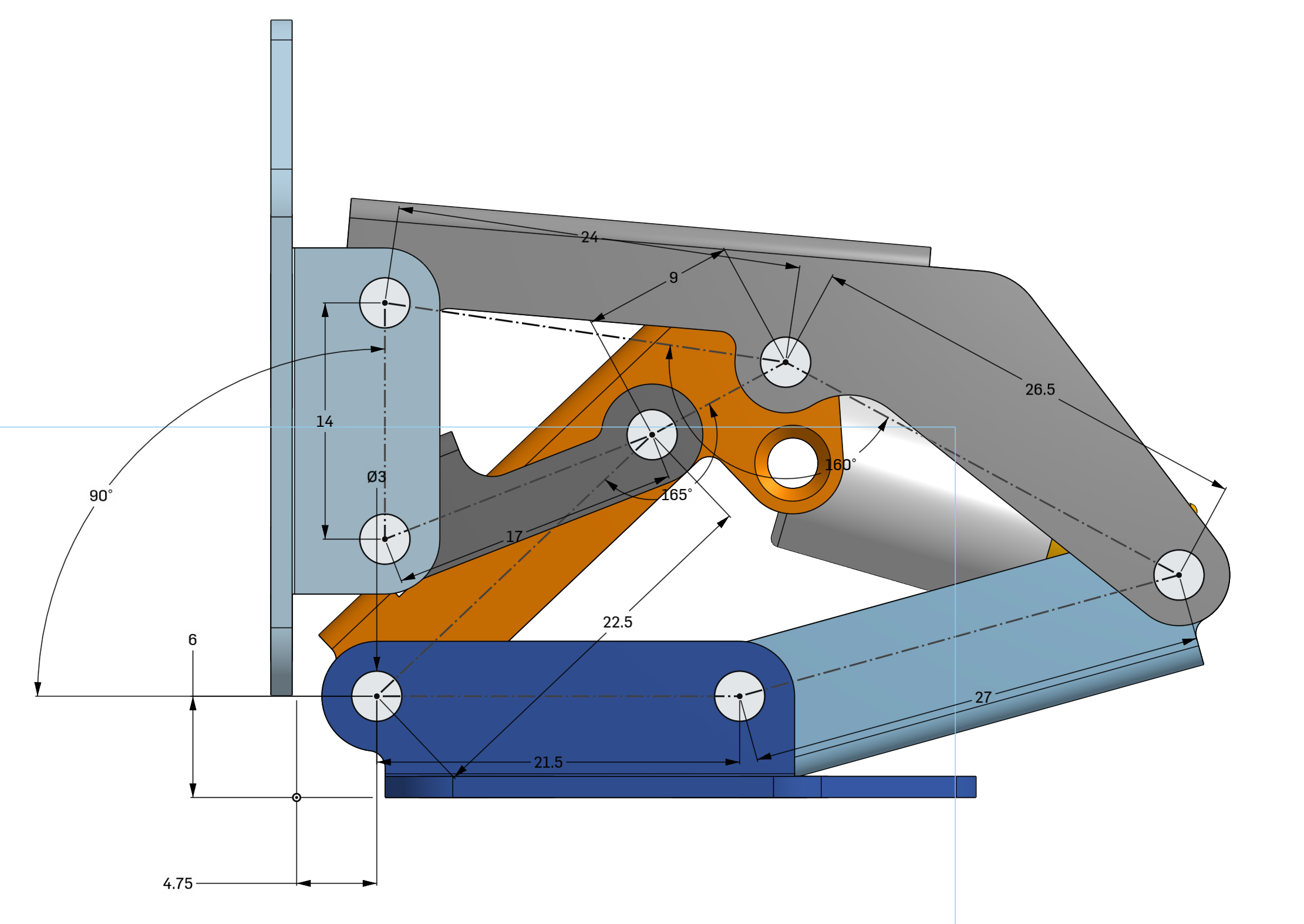
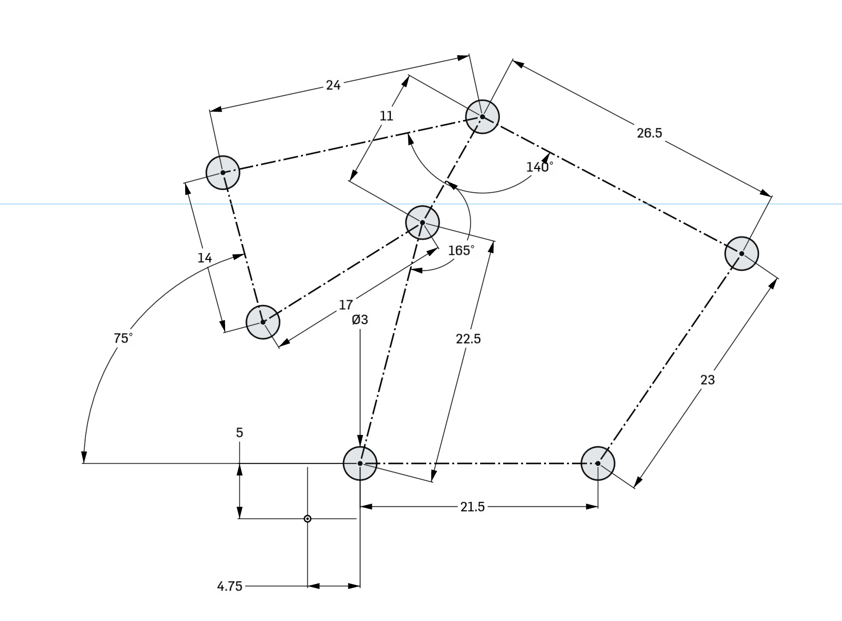
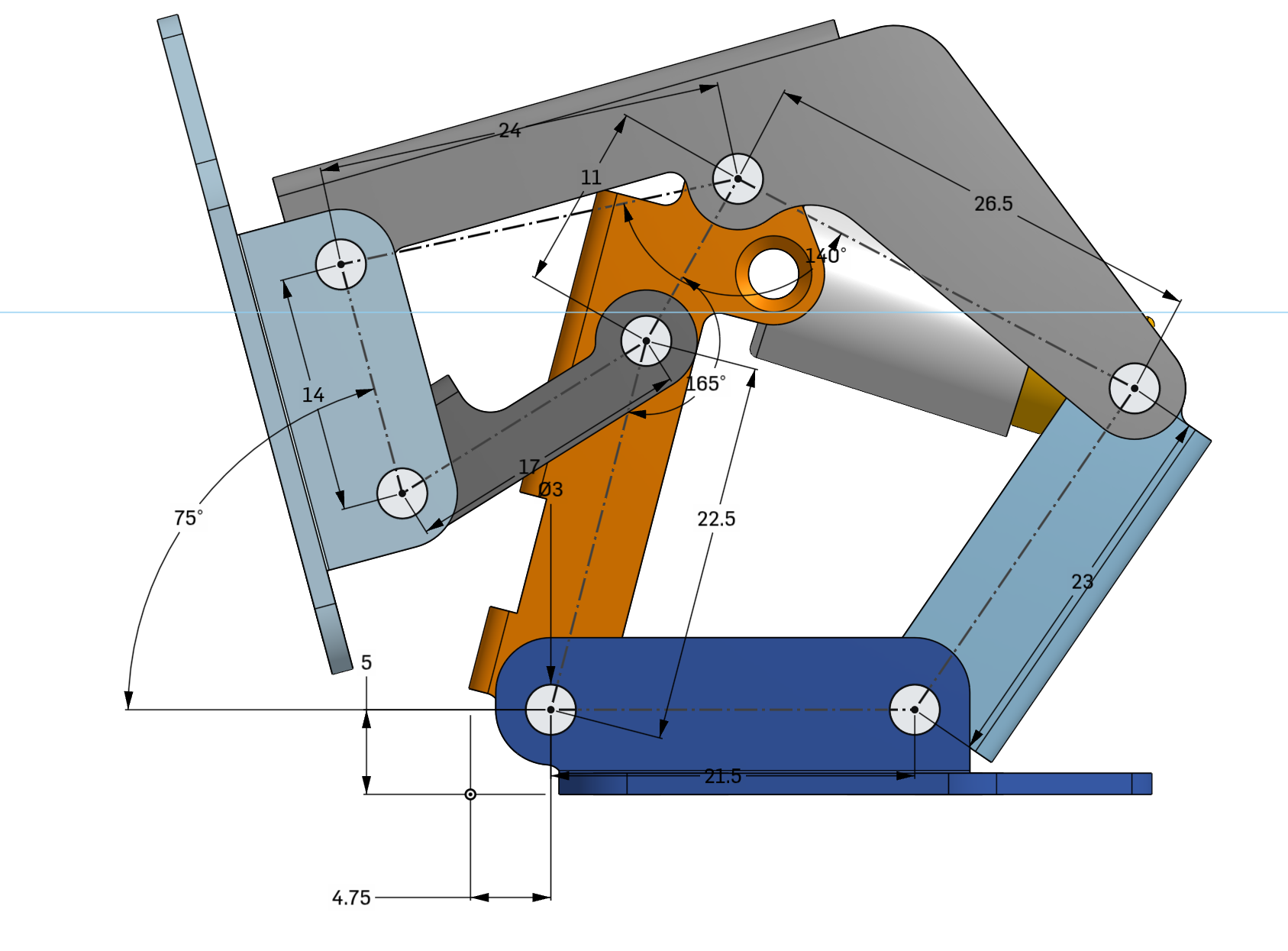
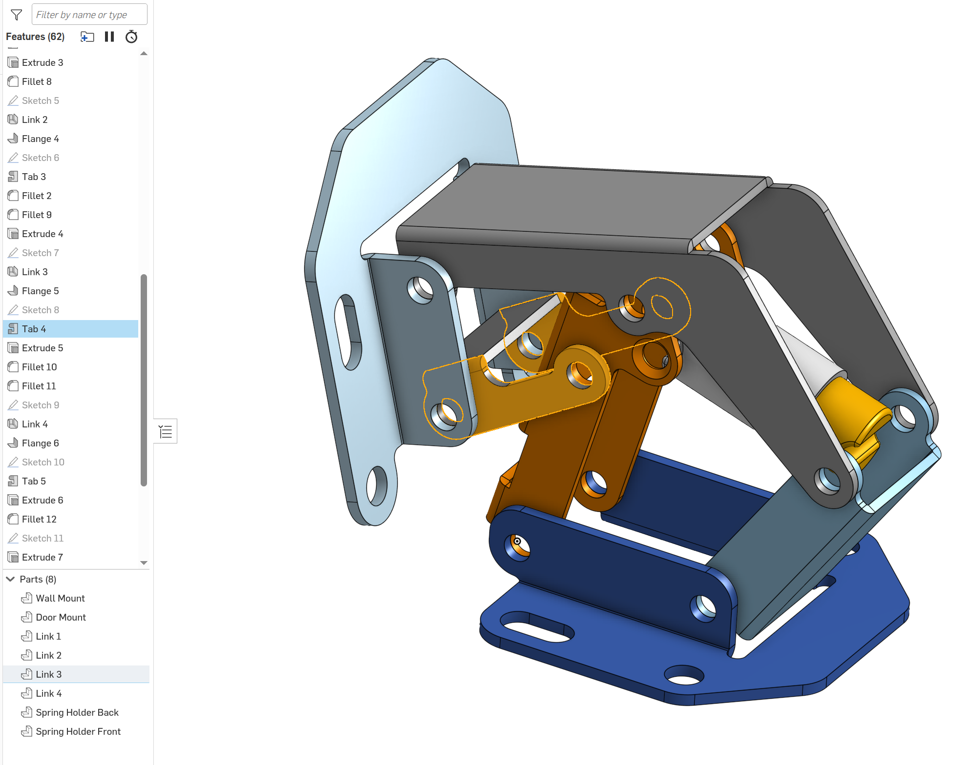
As an example of this:

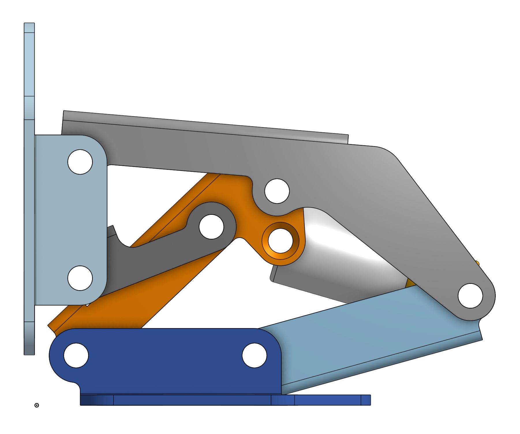
Here's a hinge mechanism: https://files.catbox.moe/06g9cg.png

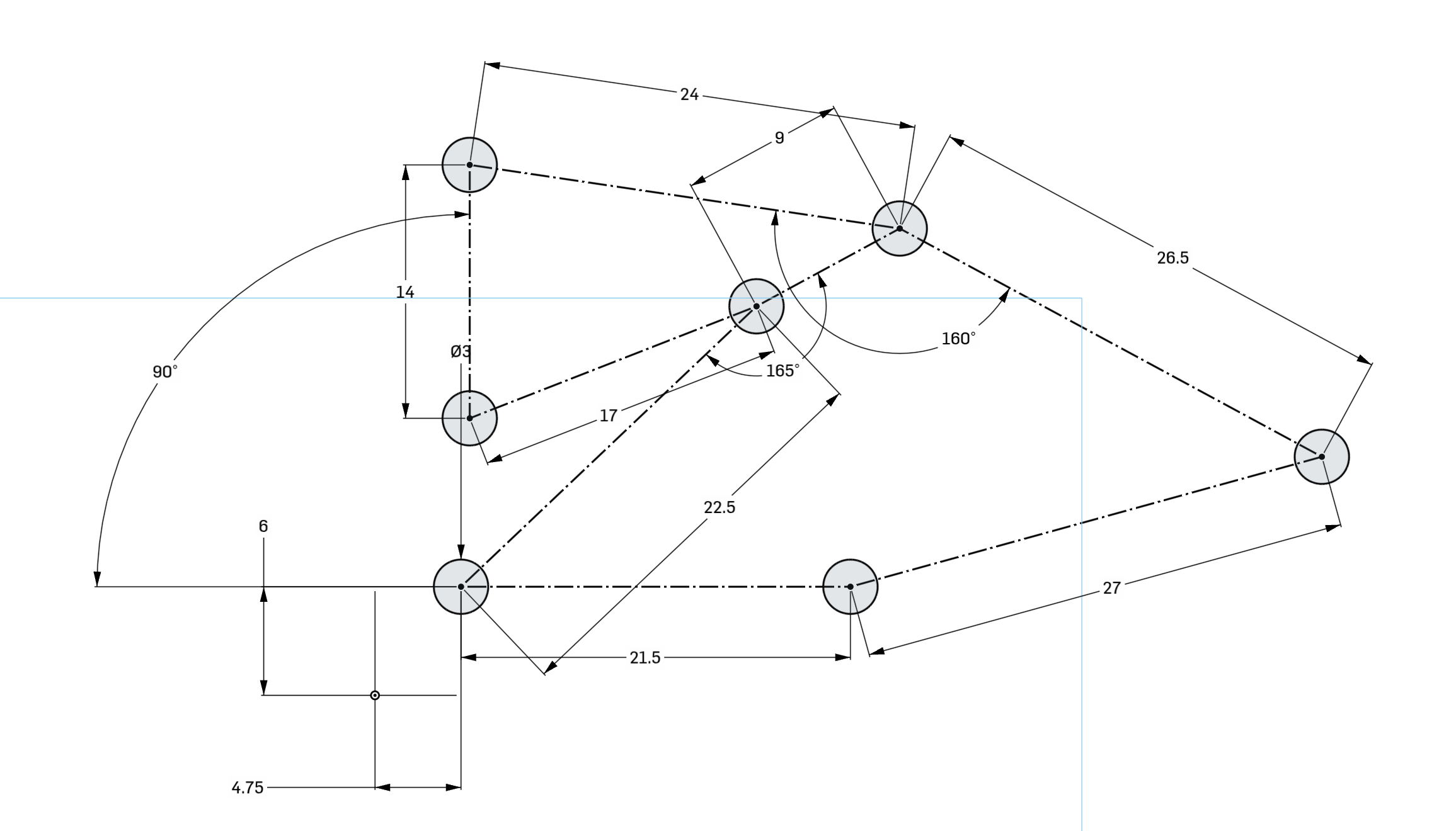
Here's the very first sketch in the timeline, I've just clicked on this to edit it, there was no undoing required: https://files.catbox.moe/xzr3un.png

Here it is overlaid on the model, which just requires a single mouse click to toggle: https://files.catbox.moe/339fvg.png

Here it is after I changed a bunch of numbers: https://files.catbox.moe/pvykrx.png

Here's what it looks like when I press the button to show the final model again: https://files.catbox.moe/6bjc0c.png

Just like that the entire model has changed based on the initial sketch. I didn't have to go edit any other features here.

As a bonus here's the assembly being moved by dragging the mouse after those changes, showing that this might not be the most well-designed hinge after those changes: https://files.catbox.moe/eztkja.mp4

Also here's the timeline I mentioned, you can see how I've clicked on a feature and it shows me exactly what it did, this also works when clicking on part of the model: https://files.catbox.moe/f0bb2k.png

Re: I designed my LED matrix PCB with code

#46
post #40

Earlier quoted context omitted.

I can only talk about my own experience trying to learn FreeCAD for a project[1] I eventually used Build123d for. For me FreeCAD was highly unintuitive. Everything is a chain of operations/modifications on solids(good!) but for some reason it won't let you modify anything but the last element in the chain? I was working on a trackball device so part of the parameters are the size of the trackball you'd use.. This aff…

The only thing FreeCAD has going for it is that it's free, everything else about it is far behind the serious commercial tools. > Ideally I'd like to see some sort of editing graph where you can see intermediate steps and pick visually parts to operate on for the next step - all underpinned by a concise textual representation that can be versioned. This is exactly how most[1] commercial 3D CAD packages have worked fo…

Well, like I said: From open tools I had available b123d was the one that relatively quickly (within a weekend from picking up the tool) allowed me to mock up something to the point where I became confident enough to keep going.

I tried to do that with FreeCAD without too much success. I assume someone proficient with it could probably crank out the whole thing within an afternoon, but not me.

I'm sure professional tools are many times more productive, but you need to spend thousands of dollars and presumably months if not years of training to become proficient in them.

And admittedly that's more of a weird hangup of mine but to me it also sort-of misses the point to use a proprietary tool for building an open source project. No one without the tool could open the source files and make modifications.

Re: I designed my LED matrix PCB with code

#47
post #37

Earlier quoted context omitted.

Layout is a puzzle, especially with particularly high density layouts, but some of this is ameliorated by high layer count and fine trace/space boards becoming cheaper. Definitely not black magic. RF layout is black magic, let's not steal their thunder here.

High speed PCBs are RF. At high enough frequencies, traces become waveguides, and the result cannot be predicted analytically. Simulation is your only light in this mess.

I have been lucky to not have to lay out anything that had frequencies of interest over 1Ghz or so. What's your experience been? E.g. types of signals, frequency range, issues you ran into?

Re: I designed my LED matrix PCB with code

#48
post #40
post #24

A lot of deserved criticism in the comments here tonight, but more generally, I have to ask - what's the deal with all these code/text to CAD/PCB things? There's a half dozen of them in any category, they are all different, they all seem to struggle badly with anything outside of simple examples, none of them appear to consider how things fit together in the real world, you almost never see any of them used for anyth…

I can only talk about my own experience trying to learn FreeCAD for a project[1] I eventually used Build123d for. For me FreeCAD was highly unintuitive. Everything is a chain of operations/modifications on solids(good!) but for some reason it won't let you modify anything but the last element in the chain? I was working on a trackball device so part of the parameters are the size of the trackball you'd use.. This aff…

> For me FreeCAD was highly unintuitive. Everything is a chain of operations/modifications on solids(good!) but for some reason it won't let you modify anything but the last element in the chain?

This has been a longstanding issue in FreeCAD. A big issue is that it is really difficult algorithm-wise to deal with changing geography: a tiny change might result in two objects which look the same, but have a completely different internal representation. If the next operation is attached to "face #23", it's going to freak out. This is called the "topological naming problem"[0], and it is pretty much impossible to solve completely.

FreeCAD itself can support the kind of parametric modeling you want, but because it's so fragile the UX is pretty horrible. To do it properly you essentially have to specifically design your entire model around being parametric from the start.

Luckily FreeCAD made some massive improvements in 1.0, and issues due to topological naming are now far less likely to occur. Hopefully it'll eventually turn from "guaranteed to ruin your day every time you try altering something" to "might need some manual adjustment in weird edge cases" - and that would also make it far more sensible to invest in UX for making mid-change modifications, or for modeling using variables.

[0]: https://wiki.freecad.org/Topological_naming_problem

Re: I designed my LED matrix PCB with code

#49
post #24

A lot of deserved criticism in the comments here tonight, but more generally, I have to ask - what's the deal with all these code/text to CAD/PCB things? There's a half dozen of them in any category, they are all different, they all seem to struggle badly with anything outside of simple examples, none of them appear to consider how things fit together in the real world, you almost never see any of them used for anyth…

They're aiming to recapitulate the success of HDL design in the IC world. The jitx folks are pretty clear about that. There are a lot of problems with that that could be a medium-sized think piece, but some things folks are doing in the space are neat. PCB-level EDA is overdue for better design checks, for example.

> PCB-level EDA is overdue for better design checks, for example.

The software itself is perfectly capable - the problem is in the source data. The industry-standard data format is "datasheet PDF written by intern".

If you want better design checks you need someone to manually read and interpret a whole bunch of nonstandard and confusing datasheets, and enter it into your EDA software. And no, LLMs won't save you here: the tiniest detail is critical, and due to the habit of using one datasheet for a whole family of chips they are often self-contradictory to a casual reader.

Alternatively, get hundreds of competing manufacturers to agree on a single data exchange format, and get them to rewrite their documentation for a few decades worth of parts into that format - for free, with zero additional sales.

Re: I designed my LED matrix PCB with code

#50
post #29

Atopile is another thing in the circuits-as-code space: https://github.com/atopile/atopile As a half EE/half SWE I think there are significant benefits to circuits as code but I'm not impressed with this one. Atopile has a narrower focus (autorouters are really really hard) and doesn't use as many buzzwords. Like why on earth does a "web first approach" matter at all for hardware development? But also, GUI tools are…

> I don't see circuit-as-code taking off with humans anytime soon I don't agree with this. Circuits aren't really anything more complex than anything else humanity has had to figure out. Most knowledge in this area seems solvable. Maxwell's equations have been known for a century. For whatever reason, Software Engineering and Hardware Engineering even though they rely upon the same fundamental physics, are so very di…

> For whatever reason, Software Engineering and Hardware Engineering even though they rely upon the same fundamental physics

They are completely different. Software is pure mathematics: you know exactly what goes in, you know exactly what operations it is going to do, and you know exactly what will come out. There are no surprises here, it's just a mechanical translation. If you want to, you can even prove that your code is doing the right thing.

Hardware is physical. Your components don't neatly follow mathematical models - the model is just a rough approximation. Everything interacts with everything else: a signal in one trace will impact a signal in the next trace over - or even on the other side of the board. Your PCB will behave differently if you hold your hand above it - without even touching it. Worst of all, most of your components are black boxes, and you don't have accurate models describing them! What good are Maxwell's equations if there's no way you're ever going to solve them?

You can make a reasonable estimate of how a PCB is going to behave, and you can occasionally do a reasonably-close simulation of some part of your circuit-to-be in isolation. But you need to physically manufacture it to find out whether it behaves the same in practice, and it takes weeks of time and thousands of dollars to manufacture a single prototype. You can't "move fast and break things". You can't afford to do the usual "hit a bug, change tiny thing, recompile, check" cycle you're used to from software programming, and some fancy tooling isn't going to change that reality.
Post reply on HN