Live data from Hacker News

Underactuated Rotor for Simple Micro Air Vehicles

modlabupenn.org

51–60 of 84 posts

Re: Underactuated Rotor for Simple Micro Air Vehicles

#51
post #24

Earlier quoted context omitted.

"The linkage to change the pitch of this rotating blade is way too complex! Can we simplify it somehow?" "How about we just add a simple device that associates the pitch of the blade with the torque, and let a computer figure out how to spin the motor to get the pitch we want? No linkage!" Yeah, that is dang clever.

I'm still not getting it. Wouldn't the pitch of the two sides be the same so how would that be useful? How do you control the pitch of two blades with a single motor?

Look at the hinge picture. See how the two hinge pins are parallel? Now imagine the blades turning 180 degrees. The hinge pins will now be at the "opposite" angle to before, despite that the blades are symmetrical so identical at 180 degrees to 0 degrees.

So at 0 degrees, increasing torque will, say, increase pitch of the "right-hand" blade while decreasing pitch of the "left-hand" one. But at 180 degrees it will be the opposite. This has the presumably beneficial effect of allowing the craft to climb by simply increasing rotor speed steadily (it will "wobble" a bit but in a spiral fashion which will let it climb without too much inefficiency). Put another way, this means that increasing torque at 0 degrees but decreasing it at 180 degrees allows an asymmetrical pitch to be maintained at a rotational speed which can be seen as constant (over the long term).

In other words, your intuition falls down because the mechanism is not as symmetrical as your brain wants it to be at first glance. Symmetry is an intuitive and attractive for mechanical systems, but it is actually limiting in many cases, and this is a great example.

Re: Underactuated Rotor for Simple Micro Air Vehicles

#52
post #42

Earlier quoted context omitted.

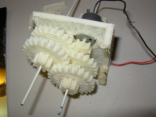
Injection molding is on the order of 10,000x more expensive if you only need a single part. I'm currently on a quest to design highly functional robots that can be made with just a 3D printer and a minimum of external parts - so far only bearings, motors, drive belts, batteries and electronics are the non-printed parts needed. I make everything so that it fits together by interlocking or with minimal use of some coar…

Seems to me that the worst part of 3d printed stuff is "the grain" is there any way to fix that?

That's a pretty big area of research apparently.

Re: Underactuated Rotor for Simple Micro Air Vehicles

#53

Earlier quoted context omitted.

1m square deskspace requirements and fast tooling in software, rather than thousands of pounds and new metal every time you want to change a detail. Injection moulding is only lower cost when you want to buy something that is already mass manufactured or millions of identical things. Up to about 10,000 units, 3d printing is cheaper.

At-home 3d-printing uses shitty materials and has terrible precision. If you don’t want to go all the way up to making expensive metal tooling and doing injection molding, you can sill get much better results from CNCing some material and then using resin casting than using a 3d printer: http://lcamtuf.coredump.cx/gcnc/

Well, I've had my 3D printer for over 3 years, and ran design and machining for an engineering shop for 7 years, and I have to say I disagree.

How do you define "terrible precision"? Is there a fixed scale in which precision goes from "terrible" to "okay" to "very good" to "excellent"?

If I'm building a telescope mirror, I guess I just ask the manufacturer for "excellent" precision, and they know what to do?

How do you classify "better results"? It is the smoothness of the part, the strength, or the cost at 5, 50, or 100,000 units? Why do resin casting when I can do lost wax casting?

Can you tell me, which manufacturing method is the best?

Oh sorry, we haven't talked about what we're making yet. Seems any discussion of tools to fabricate things is senseless until we've established what we want to make.

I'm designing a robot anyone can make at home. I mean actually, that is what I am doing as I type this comment. (well, I was designing it. It's printing now.). I want a robot that can be customized by the user. I want it to be as cheap as possible for someone who does not have access to anything more than basic electronics and a 3D printer. I want people to be able to design upgrades and test them.

Do you think I should design it so I can CNC molds that I use for resin casting? That is, after all, what you suggested.

But then, when I CNC something it takes a loooong time. First, I would design a part completely differently if I was going to CNC it versus print it. And if I was going to CNC a mold for casting, I would design it a third way still. If I am going to CNC a mold, I need to figure out where the parting line will be, and how all the molds will fit together. Some parts are impossible to cast, so I have to make sure not to design the part so as to be impossible to make with my chosen method.

Once I decide to CNC a mold, I need to source raw material that is as big as my part, but not so big that I waste a lot of material. I'll need some way to grab it in the CNC machine, so typically I choose material a little taller than my part. Ultimately it depends on how I specifically choose to make this part, and isn't strictly defined by the part's size or function.

To order raw material, if it was on short notice, I would need to go to the material store. In silicon valley across from the Fry's off Brokaw there is a place called Campbell Metal. Campbell metal is a large warehouse full of people and metals. The metals are sorted by size, shape, and length, and the people who work there tend to those materials - taking orders from the front office and cutting short pieces out of long bars. The cost of my material includes the cost of living of those people and the cost of the overhead for the large warehouse all that material is in.

Once that material is on order, I would need to program the machine to make the part. That involves figuring out the steps in order that I will use to take that raw block of material and turn it into my part. Simple parts may have 2 or fewer steps. Most have at least 3. Each one is a separate program. Once I've manually defined the toolpaths to use to make the CNC machine hollow out a block of steel or aluminum, including choosing how to send the tool into the metal, how fast to spin it, how quickly to move it, what depth and width of the tool should make a cut, I can begin to set up the machine to cut the first step. This involves taking all the right tools from the shelf, out of hundreds of possible tools, and loading them into one of the 24 tool pockets on our machine.

The machine, a HAAS VF-2SS, cost my employer around $90k. They sell a couple million dollars a year in custom made tools, so they could afford to pay this off over 5 years. I was pretty lucky to get my hands on that every day.

I could go on about the casting (get a scale, mix up material by weight, cast it), but I hope you see my point.

There is no "best" technique for "makin stuff", because every part is different. When I designed a waterproof housing that was sent 3km underwater to deal with the Deepwater Horizon oil spill, it was made from super thick aluminum with steel reinforcement. But when I designed the power button for our custom android tablet, which included software I wrote to help lift a nuclear cooling tower, I used dinky Delrin plastic for the part. There is no one best material either.

3D printed parts have certain properties. 3D printers have some limits. But what they lack in quality they often make up for in simplicity. If I had decided to print the part above instead of cast it, I'd have just made sure the thing was full and then hit "print". When I need to change something about the design, like I did this morning, I repeat that process. Iteration is a million times easier with 3D printers, which means designers can spend more time refining their parts.

For the robot I am designing, anyone with a 3D printer and the most basic of electronics can build a robot. I know where 3D printers are strong and where they are weak, so I design my parts to take that into account. They are chunky, and I leave a lot of room for the wide tolerance of home printers, but the parts work.

My 3D printer, when poorly adjusted like it is now, can hold maybe 0.040" of tolerance on a part. When I worked at the machine shop, my day to day realm was within 0.005" tolerance. On a critical part like a bearing seat, we'd add another zero to that. But there are guys making semiconductors with moving parts like DLP chips that would laugh at those tolerances. Even the guys cutting gears on their worst day would have bested my best try, because our basic $90k CNC machines had laughable quality compared to the "real" stuff.

Everything is relative. Even hand carved bricks can build a pyramid - with the right designer.

Re: Underactuated Rotor for Simple Micro Air Vehicles

#54
post #26
post #8

Now if we could just start printing these parts at home...

Seriously, why? Injection molding has far lower cost, higher quality, and you're talking about things that are very cheap and easy to ship. What does 3D printing bring to this?

" .. at home".

Experiment and explore without the wait for Mr. FedEx.

Re: Underactuated Rotor for Simple Micro Air Vehicles

#55

Earlier quoted context omitted.

At-home 3d-printing uses shitty materials and has terrible precision. If you don’t want to go all the way up to making expensive metal tooling and doing injection molding, you can sill get much better results from CNCing some material and then using resin casting than using a 3d printer: http://lcamtuf.coredump.cx/gcnc/

Well, I've had my 3D printer for over 3 years, and ran design and machining for an engineering shop for 7 years, and I have to say I disagree. How do you define "terrible precision"? Is there a fixed scale in which precision goes from "terrible" to "okay" to "very good" to "excellent"? If I'm building a telescope mirror, I guess I just ask the manufacturer for "excellent" precision, and they know what to do? How do y…

First things first, I never suggested that you personally should use any particular fabrication method for any particular purpose. In the chain of ancestor comments to my post, none of them have anything to do with you specifically.

With that said, I don’t think you looked at the resource I linked, which has some great advice for using a CNC mill to make high-precision parts via resin casting. Nothing in its advised method involves milling metal. The design involved might be slightly more difficult than designing parts for 3d-printing, but it’s not inordinately more difficult.

I personally find home-3d-printed parts to be very slow to print, expensive to print, ugly, brittle, and entirely ineffective for many things I’d want to do with them (art projects, mechanisms, housings for electronics projects, small pieces of furniture, etc. etc.). Everyone I know who has tried to do 3D printing at home spent much more time fixing and babysitting their machine than actually making stuff (and most were ultimately unsatisfied with the quality of their prints). The process is by no means “simple”.

- For a one-off part, it’s often possible to directly CNC mill something out of plastic, wood, or some other material that is vastly superior in quality and can be made just as fast or faster than a 3d-printed part.

- For trickier shapes or stuff you’re making multiple copies of, the resin casting process in the link above should often be pretty effective. Compare https://farm5.staticflickr.com/4049/4501639683_37351127de_o.... to http://farm4.static.flickr.com/3487/3703543046_b9588e64b6.jp... or for a detailed point-by-point comparison see http://lcamtuf.coredump.cx/gcnc/ch1/

- Sometimes a few flat pieces of wood, sheet metal, or acrylic cut on a laser cutter or waterjet, or using manually operated tools is a better option than CNC milling something.

- For certain other parts, I’ve seen reasonable results ordering from Shapeways or some similar place.

There might well be particular cases where home 3d printing is the best answer, but nothing that I’ve personally run into.

In any event, do whatever works for you!

Re: Underactuated Rotor for Simple Micro Air Vehicles

#56

This thing is so nimble in the air yet has a fraction of the complexity of a regular helicopter. I wonder if this method will scale up to "full size"?

Probably not, for the same reason that a quadcopter doesn't really scale to full size. The inertia effects of larger rotors make changing the speed of the rotors within a rotation much harder. With full sized helis, it takes a long time to spin up the rotors to speed before the pitch is changed to take off.

Not quad exactly but still worth following is this man lifting multicopter from Germany:

http://www.e-volo.com/

https://www.youtube.com/watch?v=CzP0Zqxam7E#t=76

Re: Underactuated Rotor for Simple Micro Air Vehicles

#57
post #51

Earlier quoted context omitted.

I'm still not getting it. Wouldn't the pitch of the two sides be the same so how would that be useful? How do you control the pitch of two blades with a single motor?

Look at the hinge picture. See how the two hinge pins are parallel? Now imagine the blades turning 180 degrees. The hinge pins will now be at the "opposite" angle to before, despite that the blades are symmetrical so identical at 180 degrees to 0 degrees. So at 0 degrees, increasing torque will, say, increase pitch of the "right-hand" blade while decreasing pitch of the "left-hand" one. But at 180 degrees it will be…

I got that part, I just didn't get the "informational control problems" comment.

Re: Underactuated Rotor for Simple Micro Air Vehicles

#58

Earlier quoted context omitted.

Well the critical difference here is that changing blade speed is not needed or desired. They just need to change blade torque, which would apparently immediately cause a change in blade pitch. I don't see a specific reason why this wouldn't scale. I do wonder what changes in load do to the system though. If it can't handle changing loads without messing up the blade dynamics, it would only work for fixed payload sys…

It won't scale because of inertia. Rapidly changing the speed/torque of a large combustion engine is nearly impossible. It's a great solution for reducing mechanical complexity in mini/micro sized UAVs, though.

You could couple a high power combustion motor with a relatively low power electric motor via a differential, and have the electric motor do the 'high frequency' modulation the combustion motor is incapable of.

With a regenerative approach, you'd probably need very little net electric power.

Re: Underactuated Rotor for Simple Micro Air Vehicles

#59
This is such a neat idea, but I wonder if it suffers from vibration problems. Because the blades are mounted on pivots, whenever you've commanding differential pitch, the high angle-of-attack blade will incur more drag and so lag slightly more than the low angle-of-attack blade. Thus the blades won't be exactly opposite each other anymore, creating vibration. Perhaps the blades are spinning so fast this is not a big deal? Probably would be if you scaled up though.

Re: Underactuated Rotor for Simple Micro Air Vehicles

#60
post #15

This thing is so nimble in the air yet has a fraction of the complexity of a regular helicopter. I wonder if this method will scale up to "full size"?

Electric motors remove a lot of the complexity in powered-lift flying machines. As soon as your power/endurance requirements demand a combustion engine, you also have to manage the complexity of a piston engine or turbine (jet) engine. This means either including a crankshaft and optionally a system of gears to route the rotational power along the axes you want the rotation in, or ducting the output of a jet turbine…

or you can generate electricity with a combustion engine a move two electric motors... like the railroads
Post reply on HN